Indoor navigation in large buildings with iBeacon technology
1. What is iBeacon technology?
iBeacon is a protocol developed by Apple and introduced at the WWDC in 2013. It is based on Bluetooth low energy proximity sensing by transmitting a universally unique identifier, picked up by a compatible app or operating system.
The identifier and several bytes sent with it can be used to determine the device’s physical location, track customer’s’ location, or trigger a location-based action on the device such as a check-in on social media or a push notification.
2. How can we use iBeacon technology for indoor navigation?
Depending on the application we may need different accuracy of the estimated position. For indoor navigation in a big shopping center or airport, it would be enough to find a room where a user is located, while some other apps would need centimeter‑level accuracy.
So, a first case is pretty straight-forward. It would be enough to have only one beacon for each room. We will just need to find the beacon with the highest `proximity` value and in most cases, it will define a user’s location.
Though there may be a false result when the user is relatively far from the beacon in a large room, but is close to the wall, where another beacon is located. In this case, the distance causes more attenuation of the true beacon’s signal, then obstacle does to the false one. To avoid it we can just put several beacons in relatively big rooms.
When high-level accuracy is needed, we can put more beacons in each room and solve and estimate user’s location by triangulating its position against known beacons’ locations. This is very similar to one of the ways of mobile network geolocation, where positions of cell towers are used instead.
Here is a simplified idea of the algorithm. Distance to each tower defines a circle of possible user locations. The intersection of two circles determines only two possible locations and a third circle defines one of them. A real-world case is a bit more complex since due to measurement error we have to deal with rings of some width instead of ideal circles.
In order to solve triangulation problem we need to:
- Place at least three beacons in each room, ideally without obstacles.
- Estimate the distance for each beacon in range.
Unfortunately, iOS SDK doesn’t provide any estimation of the physical distance to the detected beacon. All we can use is rssi (signal strength), accuracy (one sigma horizontal accuracy in meters) and proximity, which may have one of the following values:
Unknown: The proximity of the beacon could not be determined.
Immediate: The beacon is in the user’s immediate vicinity.
Near: The beacon is relatively close to the user.
Far: The beacon is far away.
But can we roughly estimate the distance using rssi value? It depends on the distance and obstacles between mobile device and iBeacon itself. Let’s imagine an ideal world without obstacles for a moment.
We can measure rssi values at different distances and then find the best fit curve to match the data points. This dependency may then be used to estimate distance for a particular rssi value.
You may wonder how does the environment affect the rssi values we get? Well, if the user is inside a steel building, there may be internal reflections, which will cause a slower fading of the signal depending on a distance. On the contrary, if there is a water (or human body) between transmitter and mobile device then the signal will be attenuated.
So, in the real world we will end up with equations based on distances to beacons, which don’t necessarily have a mathematical solution. This problem may be partially solved by increasing the number of beacons in each room and picking the most accurate of them based on `accuracy` property of CLBeacon object.
3. Technology limitations and recommendations
As described above, a distance estimation highly depends on the environment, primarily on the obstacles between device and transmitters. In order to minimize these effects and make results more accurate, we should follow the following recommendations:
- Make sure that at least three beacons are available in line of sight for each point in a room. This means that we will need more than three beacons for non-convex rooms.
- Place beacons to the ceiling, so that signal doesn’t interfere with furniture and other obstacles
- Calibrate each type of beacons separately. Signal strength also depends on the model
4. Pathfinding
Ok, we have estimated user’s location, what’s next? How can we guide him/her from point A to point B? In other words, how to solve pathfinding problem?
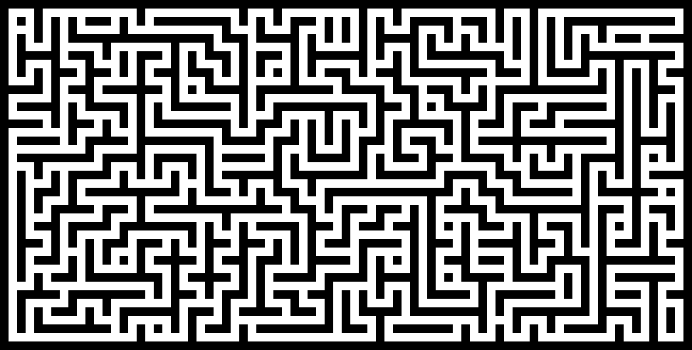
In general case this problem is defined on a weighted graph, but for the sake of simplicity let’s assume that we have a map defined by passable and non-passable squares, similar to this maze:
There are many algorithms to solve this problem, starting from basic breadth-first and depth-first, which iterates over all potential paths until the destination point is reached. A common solution is Dijkstra’s algorithm, but there is also its modified version, A* which assigns a weight to each open node, equal to the weight of the edge to that node plus the approximate distance between that node and the finish.
This approximate distance is found by the heuristic and represents a minimum possible distance between that node and the end.
5. Map generation from image
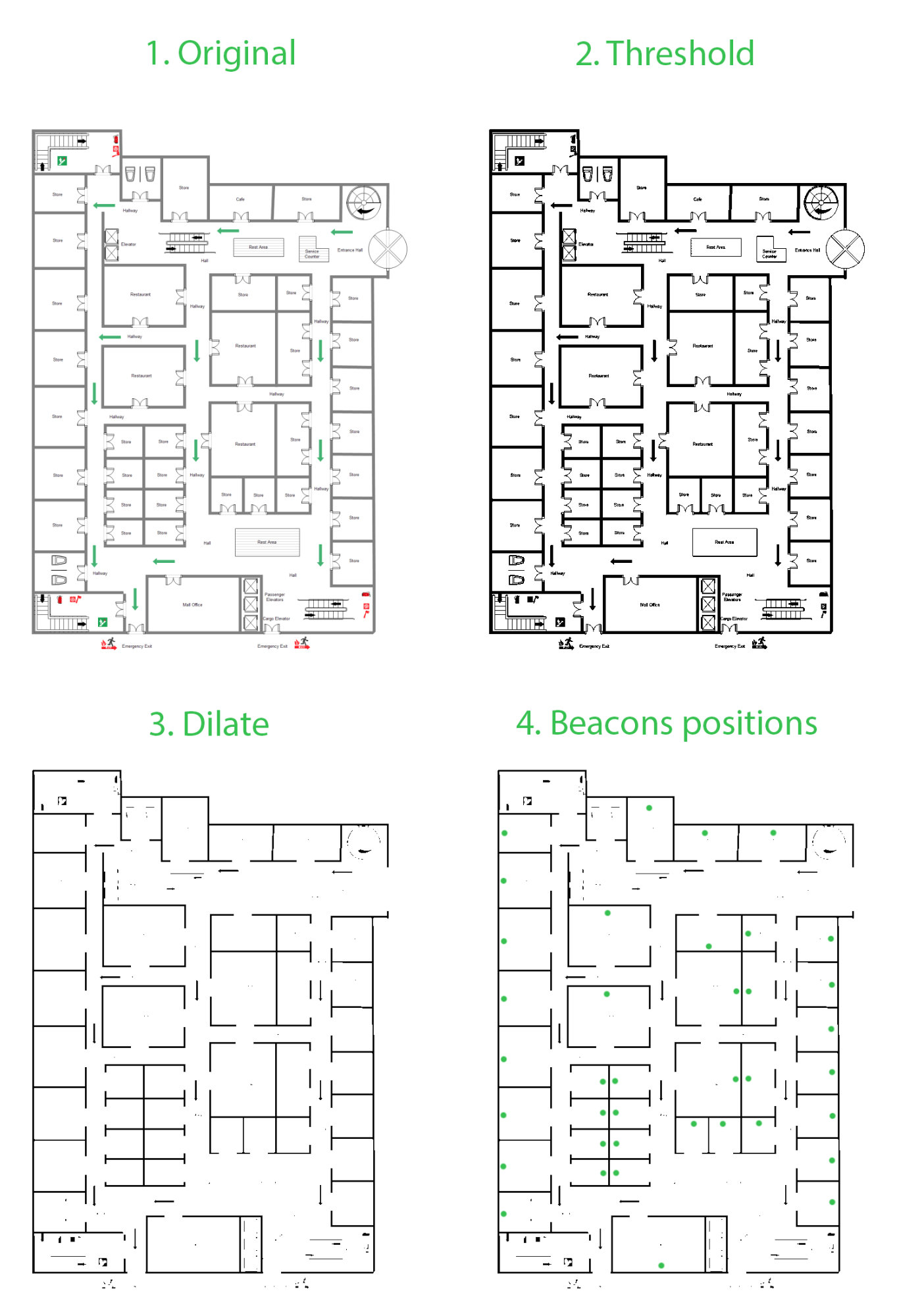
Another problem is that we need to create a map to be used by A* algorithm. How can we get it out of, let’s say, an image?
First, our goal is to get a binary image where black and white pixels correspond to non-passable and passable zones respectively.
We can preprocess input image with a couple of OpenCV functions:
- threshold() – to transform original to binary image based on some threshold brightness value.
- dilate() – to remove thin lines which should not considered as obstacles, while relatively thick lines will be preserved.
Second, let’s create a matrix of grid vertices with a certain step, which should be smaller than any door size, but big enough to keep a reasonable amount of vertices. Now we can find out if there is a path between each neighbour vertices and consider this edge a non-passable if there is no direct connection between them.
As a result, we will get a matrix of weights between neighbour vertices, which can be used by A* algorithm described above.
Thus, we’ve considered iBeacon usage for indoor navigation, an important issue for companies and organisations that need a simple solution to guide people inside large buildings. Feel free to apply to us to get more information about the topic or get a free consultation to the project.
Also find out which challenges your business can solve with iBeacon technology.